Carl M Stott
Desktop Lathe
As part of my graduate coursework in Precision Machine Design, I led my team of 6 fellow students to design, manufacture, and test a custom high-precision lathe. The project involved complex mechanical design, error modeling, and precision manufacturing techniques. I've included a video of the cut test below.
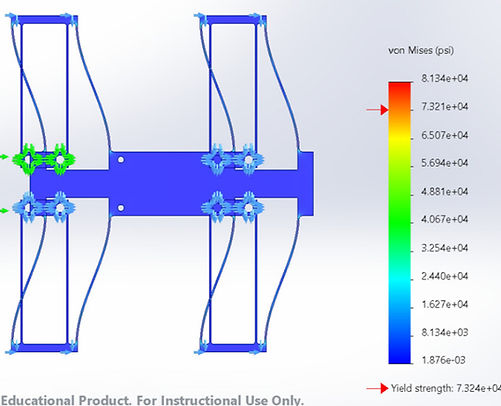
Tool Bearing Design: I developed a novel linear bearing using a set of flexures made from a single piece of 7075 aluminum. The design incorporated multiple flexure stages to allow for precise tool positioning while maintaining high stiffness in non-compliant directions. A key challenge I overcame was determining an accurate analytical model that related the bearing displacement to the stresses felt in the flexure members. Because this flexure inherently behaves extremely nonlinearly, conventional beam equations vastly overestimated the flexure stiffness and created an unrealistic relationship between flexure length and maximum possible bearing displacement. I solved this problem by finding a research paper that derived the relationship between fixed ended beam geometry and stiffness without the assumption of linear behavior, incorporated their equations into a MATLAB script that iterated across blade flexure thickness and length for a specific desired displacement, found an ideal flexure thickness/length ratio, and verified my results using FEA.
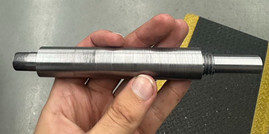
Spindle and Shaft Design: The spindle assembly went through a couple of iterations to achieve the required precision. We learned that the name of the game in shaft design was keeping the machining as simple as possible. I came up with a spindle design that allowed our machinist to create the whole shaft without needing to remove the stock from the lathe, and allowed him to create both of the <.001" tolerance bearing mounting surfaces in a single pass. Keeping fabrication simplicity in mind when designing the spindle is what allowed our team to create a spindle with a <.002" runout, which was the tightest tolerance any group achieved.
Cutting Force Analysis and Drivetrain Design: I developed a MATLAB script to optimize machining parameters. The model incorporated specific cutting energies, material properties, and geometric factors to predict cutting forces, thrust forces, and optimal spindle speed and material feed rates for cutting 6061 Aluminum using a .25 HP motor operating at 1800 RPM. The belt and pulleys were sized using the torque and speed requirements found in my cut force analysis script.